Monday, January 22, 2018

Timber Frame Shop/House 2nd Iteration

This is the second iteration of the timber frame shop/house with some major revisions. In my initial drawing, I had used a scissor truss system for the main building roof. Due to the width of the building - 36 feet, the engineer didn't feel that the scissor truss system would work very well. In its stead, he proposed using a double ridge beam that could be used to better transfer the weight and stresses of the roof directly into the foundation. This double ridge would allow use of lighter weight and much smaller rafters - a definite benefit when working at these heights. This has a major advantage for me, it reduced my reliance on longer timbers which are much harder to find. The first rafter would run from the the top plate to the ridge beam and a second shorter rafter from the ridge beam to the peak.

In addition he suggested increasing the distance between bents from 12' to 14' for at least the middle bent. This increased the width of each of the two smaller bedrooms by 1'. Not such a cramped feeling. I then suggested we do the same to the other 2 bents, so all bents are 14' on center. This helped out with a bit more space in the kitchen - 20" more space and obviously more space into the dining area.

We were also advised to figure out what windows and doors we want to have. He advised that we needed to have width of 16' of unbroken sheathing from the foundation to the roof which could be done in 2 sections of 8'. I'm unsure of whether that was on all faces of the building, just the ends but either way it was important to figure out what windows and what size windows we needed for each area and see how this lays out. I assumed 16' on all 4 sides of the building but in reality it didn't really matter because with the exception of moving 2 living room windows a little more toward the corners, it seemed to work out naturally.

I redrew the model so I had a better understanding of the structure with all these revisions. Attached are the images - the first set are just the frame - note I spent more time on the front porch this time. Though I would like the roof to overhang on the sides, just unsure how to go about that - short purlins that hang out 12-18" off the side of the rafter??

In order to save time, I did not model all the wind braces, so the side view does not contain any, which is very inaccurate.


In order to get at least some ideas on window sizes, I went to Lowes and got them to quote me on several windows in the Pella 450 series windows. I got a sheet from them that shows the available widths and heights for at least double hung windows. I assume that we can get picture window with 2 double hung (one per side) in a similar size - for the master bed and living room. Similar for the kitchen area but if we have to we would go with 2 double hung there and in the attic area. The upper window in the great room (in the open cathedral area) is going to be a picture window I believe. 

Here are the renderings with windows, I just did them in the open frames because I needed to see if they fit within the wind braces. It wasn't an issue on the side views at all so I didn't add the braces for speed purposes only.


Monday, January 1, 2018

Designing My Timber Frame Shop/House

Its been a long time since I last posted.. say about 3yrs or so. Recently my wife and I purchased 14 acres of land. One of my dreams has been to build a timber frame house and shop.

In order to see the full picture you may need to click on it.

Our plan is to build a shop first, so that I can empty out all my tools from my current garage - its not like its completely filled, I mean I can still get between equipment if I suck in my stomach and squeeze through. Honestly, I've outgrown it and I think I've outgrown the neighborhood I live in - big HOA fees and some of the highest water bills in the country.

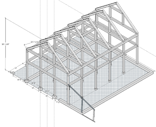
I started designing  a timber frame shop a few months ago. First it was going to be a shop that would cover all my hobbies - wood working, machine shop and tinkering on my cars.  I drew up a lot of plans and worked on a dozen different designs. Then we got thinking, hey why not have a living space above it in the loft. That put a couple of constraints on it. In the neighborhood we are moving there is a minimal living space of 1700  sq ft. That required expanding building and it grew and grew.  Friends of ours got quite upset, too many stairs to climb as we get older (2nd floor was 15'  up). The shop was going to be 36'x64' with 12' lean-to on both sides and an extension for porch on the one lean-to. Here is a partial drawing of the frame.


In the end, I went back to the drawing board at Christmas and started over. Looking at what I wanted for the woodworking shop and the machine shop. I started with a 32'x36' woodworking shop with a 16' lean-to off the one side for the machine shop. This accounted for the insulated space. Then I added a second lean-to uninsulated for storing stuff out of the weather. This design was neat but it required a 16' span between posts and that didn't appear to be a recommended spacing - unless we used really thick beams. Finding large diameter pine's locally wasn't going to be easy.. the smaller the beams the better.

We decided that we wanted to pursue putting a living space up there - at least for short term living while we sell our current house and build our final home. That could be a year it could be 10yrs. The rationale for the apartment even if we only lived there 2 years while building the main house, is it allows us to have a place for the kids to come home to. Eventually one or more will get married and visit and we aren't going to build a main house much bigger then the minimum required of 1700 sq ft. Thus having this additional living area for the kids when they come home or family visiting from out of town is really appealing to us.


Back to the drawing board.

This time I changed the layout to 36'x36' for the main shop area and 14' lean-to off the side. This basically allows 12' spans (exception being the lean-to) and that is one of the recommended spans. The age old question - what to do with the second floor reared its head once again.  Because the shop was intended for woodworking and not for automotive the ceiling is much lower. The added width gives more space into the kids bedrooms and dining area. After a lot of discussion, start overs and redesigns I came up with the following floor plans and frames.

The first thing to note is both lean-to are now insulated, the one will be the machine shop, the other side will be an exercise room, office space *away* from the kids to reduce noise and stress when I work at home. Plus no heavy desks to cart up stairs and plenty of space to store those things that will not fit in the 1296 sq ft apartment.  As this is intended to be temporary, the office area will be designed in such a way as to have a garage door framed in on the one end, then filled in for a windows for the time being. When we move into the real house, that area 14'x36' will revert to a storage shed for lumber and a tractor. We also corralled off 12'x36' of the shop into a laundry, a second 3/4 bath and large front foyer (mud room).

Yes, we are building on a slab - its meant to be a shop long term. Not a house. I absolutely detest crawl spaces and we can't afford to put in a basement and again, its meant to be a shop.

Main floor plan - left side is the exercise room/office area. The main section is the woodworking shop and the right side the machine shop and utility room, etc. The one important feature is the straight through doors that will allow materials to pass right through the building if needed.


Second floor

The kids rooms are a little tight and lack closets at present. Part of the issue with the closets is that the wind braces in the frame force the door a little bit away from the post. If we can come up with a solution that allows the door closer to the post then a small closet could be placed at the end of the bed. We may remove that divider between the rooms later and make it a bigger bedroom. It would probably be best that this go down to a single bedroom with a bonus room to keep the septic constraints realistic. So we may not put a closet in there and we may design the partition to be removable at a later date.

One of the headaches with a post and beam construction is designing around the posts and designing such that electrical, mechanical and plumbing systems are not visible.  You will note that the downstairs bathroom and laundry align directly below the kitchen and and the upstairs bathroom. This allows us to put a drop ceiling in the downstairs bath and laundry to hide the upstairs plumbing.  I'm contemplating perhaps laying down the subfloor on the 2nd floor, then doing a 2x4 frame-up on top of that to put in some sound insulation to cut down on shop noise as well as making it easier to run ceiling lights in the shop vs. having exposed wiring. But I need to talk to the engineer first and see if it even is possible and what if any the drawbacks are.

We hope to hide the bulk of the electrical in the framed interior and exterior walls. The exterior is simply an enclosure for the timber frame, it is not structural. Theoretically one can use much larger spacing on studs and even use 1x material instead of 2x. While most new timber frame construction would use SIP panels for the shell, - for maximum R-Value and air tightness, they are just way too expensive for this build - unless we decide to change up and get a large construction loan.


The funny thing with the kitchen, my wife actually gained both counter and cupboard space over her current kitchen. Though it is a gallery kitchen but should be room for two people to work easily in there.

I drew up the actual frame in Sketch Up.

ISO View

Front View:


Side View
Back View


The front view lacks the porch, its on the back of the house depending on your view of the front vs the back of the house. The side that anyone would enter is actually shown as the front of the house and faces somewhat towards the east. The back of the house faces somewhat towards the west and what little sunset we will get.

When I'm working, I like to take a break, sit outside the garage in a chair and stare off at the distance. Currently that means stare at the road and the house across the street. If its raining.. well can't sit out there. In this building, sitting outside the back door will mean sitting under a covered and possibly screened in porch. I might even make a couple of rocking chairs and get an old whiskey barrel to lean my shotgun against... maybe I'm getting too rednecked.

We probably should put a little overhang outside the main entrance as well, where people come in. But this porch is my porch.

I have a professional engineer lined up to review the above drawings over the next couple of weeks and tell me whether any of what I have designed will even work. He will probably want to shoot me over the porch, it was a late addition to the drawing and I was trying to avoid having it hit the main posts at the same intersection as the tie-beams and joists.

There will be an unfinished loft area over the bedrooms and kitchen. The great room will be exposed to the cathedral ceiling. We chose to put a ceiling in over the bedrooms and kitchen to keep things simple. I really do not want to extend walls in the bedrooms etc all the way to the roof. Someday maybe we finish it off, but for now it will be strictly for storage.

We plan to use in floor hydronic radiant heating - basically PEX water lines with 85 degree F water running through them. We may eventually put in an outdoor wood furnace/boiler to reduce our reliance on electricity or propane to heat the house.  We have 7 acres of woods to get deadfalls from etc. That and lots of off-cuts from building two timber frame houses another garage, chicken coop and maybe a small barn for a cattle beast that can keep our front field (5 acres) mowed. Its also possibly to use some solar water heating tubes depending on whether we build too close to the trees or not.


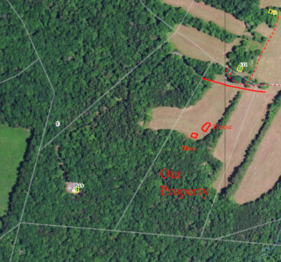
We have plans for a small orchard and large garden along the western property boundary. The left side of the picture above. The property boundaries are very rough and inaccurate in the picture above. The solid red line at the top shows the north end of our property. The lines up there are completely out of whack. Also the property is a bit more shifted to the left at an angle. That strange green dot in the adjacent property is a cell tower. Completely invisible to us but excellent cell reception.  The property is supposed to have access to fiber optic internet and fiber cable runs in the easement at the front of our property.

We plan to run our driveway down the right side of that pointed tree line in the middle of the property then cut over to the other field. Since it appears the true property line is much closer to that tree line there should be just enough room for the driveway.  The corners of the property are well marked, the problem is its impossible to see from the back of the property to the front - 1300-1400 ft through trees.

The current plan is to work in phases. Because it will be a residential building (at least initially) and I expect for a number of years. It will have to go through the design with the professional engineer. We will need to design the septic system and get the septic and well permits in hand before we can get the building permit. The neighborhood has an architectural review requirement so that has to happen first before we go too much further.


Friday, June 27, 2014

Designing a Mission influenced living room chair

I had a client approach me a couple of weeks ago asking whether I could build her a living room chair in a 'sort of' Mission style like the Morris chair but different. She had a catalog with a picture of a couch in which she wanted some of the style/features incorporated and she had a piece of existing furniture that she also felt needed to be used in influencing the design / finishing touches. Trying to word how she put it.. sort of "feminizing" the Mission style a bit by adding more curved elements to the style.

I modeled it in SketchUp last weekend and incorporated some of her feedback on that into a final model. Currently the model doesn't include any of the joinery but for the most part it will be standard mortise and tenon joints with the exception that there will be no through mortises on the arms. Here are some of the renderings from SketchUp. I didn't include any of the final finishes that she requested like the amount of round over on edges and so forth as that will stylistically be finalized once she sees the dry fitting of the chair and the amount of round over on various practice pieces.

The chair will have a platform for the seat cushion to sit on at the bottom. She preferred that over an integral frame inside the seat bottom - frame and webbing. She wanted to have cushions that would be able to have the covers taken off and washed if needed.  The one issue I have to solve at this point will be the slope of the seat platform. The back is a little more upright then my current Morris chairs so that may mean adjusting the two cleats that the platform sits on. Since the inside dimensions of my chair will be the same as hers I hope to be able to take my seat cushions and using cleats attached to the chair by clamps adjust the slope to match the back to her personal comfort.


Sunday, September 29, 2013

Bridgeport Mill - Cleaning the 3-Phase motor

My eldest son suddenly showed some interest in using some of my machine tools as he picked up a project from work that involved drilling and tapping 4 6-32 holes at 90 degrees to each other  into the circumference of a spindle. In order to do this we needed to make a jig to facilitate the process. This was the first time we really ran my Bridgeport mill for a lengthy period of time. It worked flawlessly the first night, but when we went to use it the second night it would not turn on and would blow the overload reset on the VFD I have controlling it.

At first I figured it was a bearing, though I was scratching my head because it made no abnormal noises the night before and I would have expected to hear something before the bearings totally seized up. After taking the motor off we found we could turn the shaft by gripping the pulley but it required significant effort. I received a lot of great counsel from the folks on the Bridgeport Mill Yahoo group. I checked the resistance on the 3 leads going into the motor with a multimeter - realizing fully that this is only a partial test but not having a megger it was the best I could do. Everything appeared okay to my novice eyes. 

I then pulled the top housing off and as soon as I separated it slightly from the main stator housing it spun freely on its bearing - definitely not ceased. Similarly when separating the bottom housing from the main stator housing it too spun on its bearing quite freely. I was a bit confused as I had figured it was a seized bearing. 

On this particular motor the top housing contains a greased bearing (external zirk for greasing it) and it has a plate behind the bearing towards the rotor. This plate is screwed on with 3 screws from the top of the motor. If you don't take out the screws then the rotor will come out with the top housing. The bottom housing does not need to come off to service the top bearing and the rotor. Not the less I took it all apart before I fully realized that :-)

The problem actually appears to be gunk having perhaps fallen into the gap between the rotor and the stator as seen in the picture below. The rotor has heavy dirty grease on its side. The inside of the stator also had similar deposits.

I did my best to clean the rotor and the top bearing and plate as well as the top and bottom housings with mineral spirits, careful to not soak the rotor in the mineral spirits, not sure if it would matter but thought it best to not take a chance. For the stator I used a cloth soaked in Denatured Alcohol and wiped the stator surfaces and any loose crap on the winding insulation leading to the stator. Figured denatured alcohol would evaporate much faster then mineral spirits leaving less likelihood of something shorting out there - no idea if that is true, just my thought process (I'm sure someone will laugh at me).

I cleaned all the grease out of the top reservoir, even replaced the zirk. Did my best to repack the bearing with grease and then reassembled the top housing making sure all the shims were in place first (see pictures of housings). Then filled the top reservoir with grease until it came out the plugged hole used to push out the old grease when doing a "grease change" once a year (according to the motor plate). I bolted the bottom housing to the stator housing then carefully lowered the rotor and top housing back into the stator after adding the shims to the bottom housing. Tightened up all the bolts (ughh, broke one, so back apart and drill out the broken bolt, then reassembly. I also replace the zirk and the 3 screws holding the reservoir bottom plate. 

I remounted onto the mill then rechecked the resistance to ground and to each lead with the multimeter again. All seemed well, so I hooked it back up the VFD and cringingly hit the start button. The motor started right up without any hesitation and spun up and down through the whole range of the variable speed on the VFD. 

It took me about 4 hrs in total - including cautious disassembly, cleaning which took forever, a run to the hardware store for bolts and screws, fixing the grease gun (what a mess) and final assembly and testing.

I'm not saying this is a fix for all motors, actually I was completely surprised by the actual cause. But looking at those end housings in the before picture shows there was a ton of gunk on them - about an 1/8" thick in places so it doesn't surprise me something fell in there. I can't say how long my cleaning will last - if the grease reservoir is allowing grease to escape down the shaft eventually more might find its way into that same spot and we'll be back at square one. The cost of the repair was $5.91 for the bolts, screws and some washers - only because I bought type 8 bolts (why I don't know).

Obviously if you don't know what you are doing, be extremely cautious when messing with electrical components such as this. 


Monday, July 2, 2012

Rebuilding South Bend Heavy 10 - Part II

I've been working on the rebuild of my South Bend heavy 10 lathe for a few weeks now. Saturday I completed what I'll term phase I.

Phase I included:

  1. Remove lathe from cabinet
  2. Remove under drive and electrics from cabinet
  3. Strip, clean and paint cabinet
  4. Disassembel, strip, clean and paint under drive components
  5. Reassemble under drive (replace bearing on cone pulley shaft)
  6. Reinstall under drive
  7. Blow up old motor (okay that wasn't planned - got some paint into the motor and it just won't work.
  8. Install new motor, rewire everything using flexible conduit that is coated in pvc for sealing against oil and grease.
  9. Put it all back together - fit door to catches properly, assemble drawer locks
  10. Retouch paint where needed.
Here is a picture of the completed cabinet and under drive at the end of phase I. I still need to put on the knobs on the drawer locks - didn't want to close the drawers all the way as I did some paint touchup on them Saturday evening.


Phase II will entail the following:
  1. Disassemble the lathe into major units
  2. Disassemble, clean and strip the head stock, gear box, carriage, bed and other major castings.
  3. Paint these major pieces

Yesterday I started to disassemble the main lathe components. I got my sons to help me get it back up on the bench using the motor hoist then I began to disassemble major components off of it.  I began by removing the carriage, then the headstock and associated covers and finally the gear box and lead screw. While I had the leadscrew bearing off the end I supported the leadscrew with several pieces of 2x4 under it so that when I slid the carriage off the end that I didn't wind up bending or putting stress on the lead screw.

Here is the lathe just after putting it on the bench before starting disassembly. Most of the pictures I took during disassembly were images about position of various pieces and screws etc. 


Here are a few shots of the major pieces as they came off the lathe:


With the major assemblies set aside I proceeded to begin to strip the paint from the bed and various head stock covers using Citris Strip.


After a lot of elbow grease and several coats of Citris Strip and visits with the pressure washer over the last two nights. I now have the bed, bed feet, headstock castings, gear box assembly, all the covers and other odds and ends stripped clean. Here are some pictures of the stripped and cleaned parts. I've coated the ways in WD 40 to prevent rust and did similar things with the gear box and head stock casting - especially in bearing journals and scraped surfaces.


Here is the headstock casting and journal caps as well as the spindle. I don't currently own a gear puller so I can't take the gear off the end of the spindle in order to fully disassemble. I'l lhave to stop a TSC tomorrow after work and get one.


Here is the gear box with 95% of the paint stripped off of it. I removed the plate with the gear chart prior to stripping the paint as I didn't want to lose the paint on that plate. It was a simple process of taking an old  1/4" chisel  (bevel side up) and carefully tapping it under the pin to raise it slightly then grabbing the pins with a small pair of side cutters and giving a slight turn. They popped right out. Whole process took about 3 min. Thanks to the guys on the South Bend forum for the technique.


I cleaned the gear box first by soaking overnight in a solution of Purple Power though I'm not certain how much it really helped. Then I covered it in Citris Strip and let it sit for a half hour then blasted it off with the pressure washer. Then more Citris Strip and a second round of presssure washing. Then I spent half an hour sitting with it tipped partially into an ice cream pail with mineral spirits and washed and rewashed the gears with a paint brush.  I'm now at a crossroads as I try to figure out whether I really need to fully disassemble the gear box. I'd like to because I want to ensure all the bearing surfaces are clean but I've heard these single tumbler gear boxes can be a nightmare to disassemble and reassemble.  Waiting on some advice from the South Bend forum before I proceed.


Here are some of the other parts that have been striped. I have to hit a few with the wire wheel to get rid of the surface rust. You can see some of the parts are aluminum - gear covers. Which really surprised me. I figured they'd all be cast iron.


Well that's it for this post.

Monday, June 18, 2012

Rebuilding my south bend heavy 10 Part I

I bought a South Bend heavy 10 lathe a year ago in May. I finally got the time to start rebuilding it two weeks ago. The first picture is of the lathe as it appeared just after I got it.


It was fairly clean although the previous owner hinted that it had sat in a barn/shed for about 6 yrs. There was some clay on the feet indicating that it may have sat on a dirt floor. When I first got it home I realized that the tailstock center does not align vertically with the headstock - I believe its off by about 25 thousandths of an inch or there abouts. Because the lathe had sat around a shed for a long time and because its also sat in my woodworking shop for a year uncovered it needs a good cleaning and check out before I put it into service. I plan on getting my wife to sew me a cover to throw over it and also one for my mill.

The first step in stripping it down was to take off the front sheet metal cover and remove the drawers. You can see the accumulated dust and grim of a year of sitting around.


I removed the lathe and dropped the motor and underdrive.

I then used Citris Strip to strip off the first 3 layers of paint - various shades of gray. I took the 4.5" Makita mini-grinder with a wire wheel to remove the loosened off paint. The final layer was a dark gray/black and was a pain to strip off. I blasted the cabinet off with a pressure washer I borrowed form a friend. It required a separate coating of Citris Strip and a lot of elbow grease to get the bulk of that layer off I sanded out any remaining paint - feathering it out with 80 grit on my random orbital sander.


I tried to spray the cabinet with a small spray gun my dad gave me when he was over a week ago. But the paint specs said don't thin (Benjamin Moore P22 Urethane Alkyd Enamel) and it wouldn't spray at all. Then I tried to paint with a brush on the inside of the cabinet and that just did not work. Did a bit more reasearch and went ahead and thinned the paint and got it to spray out of the paint gun though it required a higher amount of pressure and filled the garage with overspray. Ugghh. Did I ever say I hate painting. I did just the bottom of the cabinet so that I could flip it over later and do the sides and top without worrying about the hard to reach areas. I wound up sanding a lot of it off a few days later to get rid of brush strokes and some runs.


I then disassembled the underdrive, degreased (soaked in Purple Power), stripped (Citris Strip) and cleaned all the parts up - another good use of the pressure washer (them things are handy).

On Saturday I took everything outside and painted what I had ready:

Cabinet
Drawers
Underdrive

My friend loaned me a nice Binks Mach S1 HVLP spray gun which was a pleasure to use.. though I have to admit I'm still no painting genius. I wound up putting a whole canister of paint on the cabinet and another half canister on the rest of the sheet metal and drawers. Basically a really heavy coat.  This time I did it outside and the HVLP gun was set for only 15lbs pressure. The overspray dropped like a rock around the cabinet onto plastic I had laid out. The cabinet and drawers turned out awesome!


You can see the five gallon cans I had the cabinet sitting on - I had already taken it inside before I remembered to take a picture. I used two step ladders with my long pipe clamp pipes as supports for hanging the drawers and smaller pieces on. After spraying the drawers and sheet metal I did the smaller cast pieces with just a brush. It didn't look too bad after the second coat of brush on but I have a lot of places to clean off the paint. I think I need to get a better brush before I do much more.

I cleaned up the motor and gave it a shot of black gloss paint on Sunday afternoon. It came out looking really nice (sorry no picture). 

I need to clean up the surfaces that shouldn't have gotten paint this week and then I need to reassemble the under drive and put it back into the cabinet. Then I'll be ready to start tackling the lathe itself.